Title : IR distance sensor circuit.
Objective : To test IR distance sensor circuit.
Procedure : 1) The IR distance sensor circuit had been constructed on the breadboard.


Figure
1: IR distance sensor

Figure 2: IR distance sensor
circuit connection
2) The IR distance sensor is
to detect the level of food in the small container inside the chicken coop.
Below are some illustration that been sketch to show how the IR distance sensor
circuit been applied to Smart Chicken Coop.

Figure
3: IR distance sensor pin configuration

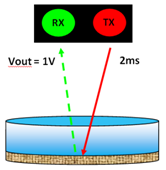
Figure
4: During the food was getting empty
By referring to Figure 4, during the food was getting empty, the distance taken from TX to transmit
data to RX is longer. When the distance is longer, the time taken to transmit
the data is longer too (eg. 2ms). Therefore the voltage is less (eg. 1V). So
the solenoid motor will open the gate to refill the food in the small
container.

Figure 5: During the
food was getting full
By referring to Figure 5, During the food was getting full, the distance taken from TX to transmit
data to RX is shorter. When the distance is shorter, the time taken to transmit
the data is shorter too (eg. 1ms). Therefore the voltage is more (eg. 2V). So
the solenoid motor will close the gate to stop the food from refill the food in
the small container.
Results
: The circuit had been tested.

Figure 6: When the distance taken from TX to transmit
data to RX is longer

Figure 7: When the distance taken from TX to transmit
data to RX is shorter
Conclusion:
The IR distance sensor circuit is function well. When the distance taken from
TX to transmit data to RX is longer, the output voltage is 0.677V. But when the distance taken from TX to transmit data to RX is shorter, the output voltage is
2.028V.
No comments:
Post a Comment