Title : Attach the
circuit and component with hardware, burned the program into IC’s and test the
water level sensor.
Objective : To make sure the hardware is suitable
with the function of the project.
Procedures :
1) The IR distance sensor circuit, humidity sensor circuit,
thermistor circuit, water level sensor circuit had been attach on the top space inside the chicken coop.
Figure 1: All the circuits had
been attached on top space inside the chicken coop
Results : 1) The components had been attached with
the hardware:
Figure 2: The thermistor had
been hanging on top inside the chicken coop
Figure 3: The bulb had been
attached on top inside the chicken coop
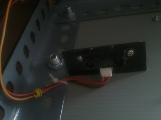
Figure 4: The IR distance
sensor had been attached on the right side inside the chicken coop by facing it
downwards.
Figure 5: The fan had been
attached on the right side outside the chicken coop
Figure 6: The water level
sensor had been attached with the water container inside the chicken coop
Figure 7: The water pump had
been attached on top of the water container inside the chicken coop
Figure 8: The humidity sensor
had been attached on the left side inside the chicken coop
2) The water level sensor had been tested. The results had been made in illustration below:
Figure 9: Illustration of water level sensor
Conclusion: All the circuit and component had
successfully attached with the hardware and suitable with its function and the
program had been burned into the IC and ready to be tested.


No comments:
Post a Comment