Thursday, September 13, 2012

WEEK 7: 13TH SEPTEMBER 2012


Title             : Designing the PCB layout using PCB designer.

Objective     : To design the PCB layout by referring the circuit                              connection and pin configuration.

Procedure   : 1) The PCB Designer Software Version1.54 had                                 been installed.

            Figure 1: The PCB Designer Software Version 1.54

                   2) By opening the software. The PCB layout had been                        start design.
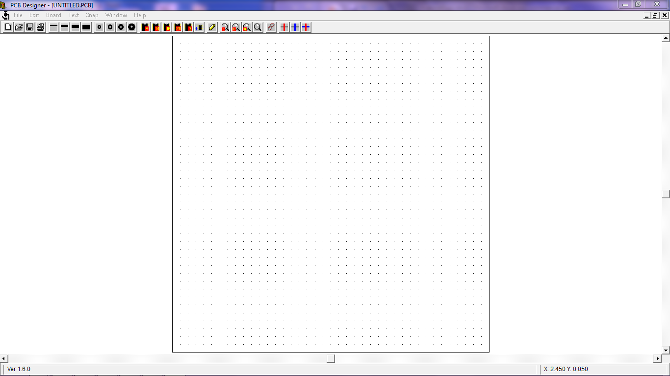
               Figure 2: The opening window of PCB Designer                   

Results      : After the layout had been done the margins had                              been adjusted so that the circuit was in the middle of                      the sheet. 

                    Figure 3: Smart Chicken Coop PCB layout

Conclusion: The connection must be design neatly without any                          cross, overlap connection or complicated design.

Monday, September 03, 2012

WEEK 6: 3RD SEPTEMBER 2012


Title            : IR distance sensor circuit.

Objective   : To test IR distance sensor circuit.

Procedure : 1) The IR distance sensor circuit had been                                          constructed on the breadboard.


Figure 1: IR distance sensor

                Figure 2: IR distance sensor circuit connection

                 2) The IR distance sensor is to detect the level of food                       in the small container inside the chicken coop.                                 
                     Below are some illustration that been sketch to                                show how the IR distance sensor circuit been                                  applied to Smart Chicken Coop.

                Figure 3: IR distance sensor pin configuration

               Figure 4: During the food was getting empty

               By referring to Figure 4, during the food was getting                        empty, the distance taken from TX to transmit data to                    RX is longer. When the distance is longer, the time                        taken to transmit the data is longer too (eg. 2ms).                            Therefore the voltage is less (eg. 1V). So the                                  solenoid motor will open the gate to refill the food in the                small container.

Figure 5: During the food was getting full

              By referring to Figure 5, During the food was getting full,               the distance taken from TX to transmit data to RX is                       shorter. When the distance is shorter, the time taken to                 transmit the data is shorter too (eg. 1ms). Therefore the                 voltage is more (eg. 2V). So the solenoid motor will                       close the gate to stop the food from refill the food in the                 small container.


Results : The circuit had been tested.

Figure 6: When the distance taken from TX to transmit data to RX is longer

Figure 7: When the distance taken from TX to transmit data to RX is shorter

Conclusion: The IR distance sensor circuit is function well. When                      the distance taken from TX to transmit data to RX is                        longer, the output voltage is 0.677V. But when the                          distance taken from TX to transmit data to RX is                              shorter, the output voltage is 2.028V.

Thursday, August 30, 2012

WEEK 5: 30TH AUGUST 2012


Title             : Designing the circuit connection using Proteus 7                             Professional and construct on the breadboard.

Objectives   : 1) To design the circuit diagram for Smart Chicken                              Coop.
                      2) To construct the circuit on the breadboard and                               been tested.

Procedure   : 1) The Proteus 7 Professional software had been                              installed.

                           Figure 1: Proteus 7 Professional

Results      : 1) The Smart Chicken Coop circuit diagram had                                  been design using Proteus 7 Professional.


Figure 2: Smart Chicken Coop schematic diagram
                  2) The circuits had been constructed on the                                         breadboard to test the connection.

Figure 3: Circuit that been constructed on the breadboard

Conclusion: Designing the schematic diagram using Proteus 7                          Professional is very important before testing the                              circuit on the breadboard. If the polarity was wrong,                        there will be short circuit and the components might                        burn.


Wednesday, August 22, 2012

WEEK 4: 22ND AUGUST 2012


Title             : Make some changes on the project block diagram.

Objectives  : 1) To finalize the project block diagram.
                      2) To buy all the components needed.

Procedure  : 1) The project block diagram had been change due                            to all the research that been made in FYP 1.
                      2) The components had been listed and been                                      bought to implement the circuit.

Results      : 1) The project block diagram had been finalized.

Figure 1: Project block diagram

                    2) All the components needed had been listed and                             been bought.

Figure 2: Project block diagram

Conclusion: Choosing the right components are very important in                      order to ensure the circuits function well.


Wednesday, August 15, 2012

WEEK 3: 15TH AUGUST 2012


Title             : Make some changes on the project component.

Objective     : 1) To change the LM35DZ to thermistor.

Procedure   : 1) The LM35DZ have to be change to thermistor.

Results      : 1) The thermistor output is non linear which is                                      suitable for this project.

Thermistor resistance vs temperature

                    2) Thermistor or thermal resistor is thermal sensitive                           resistor. It means its resistance changes with                                   temperature. This change in resistance character                           divides the thermistor into two types, depending in                         the way it responds to the temperature.

                    3)   Positive Temperature Coefficient thermistor.                               (PTC)
               ·        thermistors exhibit an increase in electrical                        resistance when subjected to an increase in                      body temperature

                    4)   Negative Temperature Coefficient thermistor.                            (NTC)
              ·        thermistors exhibit a decrease in electrical                         resistance when subjected to an increase in                     body temperature

Conclusion: The thermistor had been used to measure                                      temperature for Smart Chicken Coop because it is                          inexpensive, rugged, reliable and respond quickly.                          The thermistor that will be use is NTC 10k.

 Thermistor NTC 10k


Wednesday, August 08, 2012

WEEK 2: 8TH AUGUST 2012


Title              : Make some changes on the project component.

Objective     : To change the dc gear motor to solenoid motor.

Procedure   : The dc gear motor have to be change to                                          solenoid motor because it will be use to open                                  and close the gate of the food supplied by the                                main tank to be refill in the food container inside                              the coop.


                     Figure 1: Illustration the solenoid motor to push/pull the gate

Results      : 1) The difference between a solenoid and a motor is                          that a solenoid is spring loaded and cannot rotate.

 Figure 2: Solenoid is spring loaded and cannot rotate

2)   Solenoid basic operation
Inside a solenoid is motor wire coiled in a special way. When an electric current been sent through the wire (energized), a magnetic field is created. The inner shaft of a solenoid is a piston like cylinder made of iron or steel, called the plunger or slug (equivalent to an armature). The magnetic field then applies a force to this plunger, either attracting or repeling it. When the magnetic field is turned off, a spring then returns the plunger to its original state.

Figure 3: Solenoid basic operation

Conclusion: The dc gear motor had to been change to solenoid                        motor.

Tuesday, July 31, 2012

WEEK 1: 31ST JULY 2012


Title              : Briefing about the Final Year Project (FYP) with the                        FYP Committee at Gemilang Hall.

Objectives   : 1) To update the student about the latest news.
                       2) To highlight the important date that students                                     have to alert.

Procedure   : 1) The FYP Committee had review about previous                               FYP 1.
                       2) The mark allocated for FYP 2 consisting of:
·        Final report – 20%
·        Logbook / Blog – 20%
·        Presentation (Product demonstration) – 20%
                       3) The student had been remind to continue                                         their progress and always update the blog.
                       4) The important date that student been reminded                               are:
·        Presentation (Product demonstration) – W14
·        Logbook / Blog – W15
·        Draft of final report – W15
·        Final report (Hard cover) – W17
·        Claim – Students can claim maximum RM500 for their project together with the receipt by 30/11/2013

Results        : The final year project had been continued and any                          changes had been recorded.

Conclusion  : All student had understood and clearly been brief                            about FYP 2.